
Winding layout
The winding layout is the arrangement of the coils of each phase in the slots.
The phases are noted Aa for the first phase, Bb for the second phase, and Cc for the third phase. The capitalization indicates the conductor orientation: upper-case letters A, B, C for the conductors in one direction and lower-case letters a, b, c for the return conductors.
Example: Below is the example of a double-layer 4-pole 15-slot winding with a coil span of 3 slot pitches. Fig. 1 shows the winding layout, and Fig. 2 shows how the coils are arranged correspondingly for phase U. The winding layout does not specify how the coils are interconnected, i.e., in parallel or in series.
| A | c | B | B | a | C | b | A | A | c | B | a | C | C | b | |||||||||||||||||||||||||||||||||||||||||||||
| c | c | B | a | C | b | b | A | c | B | a | a | C | b | A | |||||||||||||||||||||||||||||||||||||||||||||
Fig. 1 Winding layout of a double-layer 4-pole 15-slot winding.
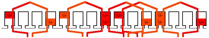
Fig. 2 Double-layer 4-pole 15-slot winding with corresponding coil arrangement for phase U.
Read about another glossary term