
Slot fill factor
Ratio between the cross-sectional area of all conductors in one slot and the entire slot area.
The slot fill factor is equal to the ratio of the conductor area over the total slot area, see Figure 1. For example, a slot fill factor of 0.5 would signify that half (50%) of the slot area is occupied by the conductors (i.e. pure copper or aluminum). The other half of the slot area is occupied by conductor insulation, slot insulation, and inevitable gaps in between the conductors and between the conductors and the slot sides.
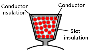
Fig. 1 Illustration of slot fill factor.
The slot fill factor depends on the insulation thickness around the conductors and the slot, as well as the conductor shape. It is usually between 0.4 and 0.6. Higher slot fill factors can be achieved with rectangular conductors instead of round conductors. Achieving a high slot fill factor also requires suitable winding equipment and special attention during manufacturing.
Often, electrical machine designers aim for slot fill factors that are as large as possible in order to increase the power efficiency. If the slot fill factor can be increased, it is possible to either increase the conductor area accordingly (and thus decrease the phase resistance and conductor losses) or decrease the slot area accordingly (and thus decrease the flux densities around the slots and probably the iron losses).
How big is the maximum possible slot fill factor using round conductors?
How much copper can you possibly squeeze into the slots of your electrical machine as a function of the conductor diameter and insulation grading?
Figure 2 shows the maximum possible slot fill factor assuming that the conductors are placed in perfect order, that the slot is infinitely large, and that there is no slot insulation. In reality, none of these three assumptions can be practically implemented, which means that you should assume lower slot fill factors than the ones provided in Figure 2. The data for Figure 2 is based on round copper wire from Dahrentrad (DAMID, DAMID PE and DASOL) and corresponds to IEC 60317-0-1 standards.
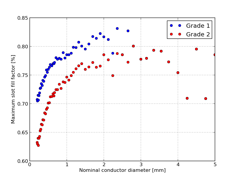
Fig. 2 Maximum slot fill factor as a function of insulation grading and nominal conductor diameter according to IEC 60317-0-1.
You should be aware that it will be challenging to arrange conductors with a very small diameter in such a perfect order as to achieve the slot fill factors provided by Figure 2. This should be considered whenever you plan to split your conductors in multiple smaller wires connected in parallel in order to reduce eddy currents caused by the skin effect. Also if you plan to transpose or twist your wires in the slot for the same reason, the maximum achievable slot fill factor will be reduced.
On the contrary, if you have conductors with very large diameters, the slot fill factor can get reduced considerably by those inevitable gaps between the conductors and the slot sides. That is the reason why the slot fill factor for conductors with large diameters in Figure 2 takes somewhat arbitrary values. In addition, the insulation grading (conductor insulation) has a much lower influence on the slot fill factor for conductors with large diameters. If you want to further increase the slot fill factor than what is possible with round conductors, you may look into rectangular conductors that allow you to considerably reduce the gaps between conductors and between the conductors and the slot sides.
Read about another glossary term