
Magnet angle
The magnet angle is provided in electrical degrees and defines the width of the surface-mounted permanent magnets.
The magnet angle is provided in electrical degrees (independent of the number of poles) and is allowed to be in the range between 18 deg ($\pi$/10 rad, 10 percent of the pole is covered with permanent magnets) and 180 degrees ($\pi$ rad, the entire pole is covered with permanent magnets). If the value of the magnet angle is larger than 3.1 rad (approximately 177.6 deg), Emetor assumes that the entire pole is covered with permanent magnets.
For example, in a 4-pole design as shown in Fig. 1, a magnet angle of 120 deg ($2\pi /3$ rad) results in a mechanical angle of 60 deg ($\pi /3$ rad).
For both the inner and outer rotor topologies, the magnet angle is defined on the inside of the magnet, i.e., towards the center of the machine as shown in Fig. 1.
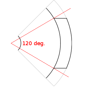
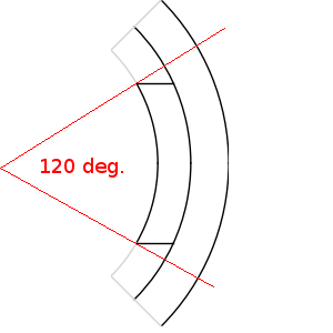
Fig. 1 Example of magnet angle definition for different rotor templates: Inner rotor with parallel magnetized magnets (left), Outer rotor with parallel magnetized magnets (right).
Breadloaf magnets, on the other side, are not defined by the magnet angle. Instead, they are defined by their magnet width and their magnet radius.
Read about another glossary term