End-winding leakage inductance
Leakage inductance of the winding end-turns.
The end-winding leakage inductance is generally rather small and depends on the actual shape and arrangement of the end-turns. Therefore, it is difficult to calculate in a general way. In Emetor, it is assumed that the end-turns are shaped as half-circles, refer to Fig. 1. This assumption has proven to approximate the end-winding leakage inductance with sufficient accuracy.
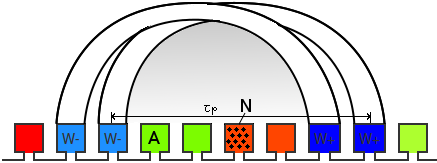
Fig. 1 Illustration of end-turns: Winding with 2 coils per group and a coil span of 6 slots.
In Emetor, the end-winding leakage inductance of a winding coil is calculated according to the following equation by Hanselman, "Brushless Permanent-Magnet Motor Design", McGraw-Hill, 1994: $$L_{end-coil} = \frac{\mu_0\tau_pN^2}{2}\ln\left(\frac{\tau_p\sqrt{\pi}}{\sqrt{2A}}\right)$$ as a function of the coil pitch $\tau_p$, the number of turns per coil $N$, and the coil area $A$ as shown in Fig. 1. For a single-layer winding, the coil area corresponds to the slot area, while the coil area is only half the slot area for a double-layer winding.
The total phase end-winding leakage inductance is then calculated taking into account the number of coils per parallel path $k_s$, the number of parallel paths $k_p$, and a correction factor $k_m$ taking into account the mutual inductance between different coils in a group of coils (as described by Hendershot and Miller, "Design of brushless permanent-magnet machines", Motor Design Books LLC, 2010): $$L_{end} = k_m \frac{k_s}{k_p}L_{end-coil}$$ The correction factor $k_m$ considers the mutual flux between a group of coils, as indicated by the shaded area in Fig. 1. It depends on the number of coils per group and the coil span of the winding. The following table shows $k_m$ values for the most common winding configurations, assuming that the end-turns are shaped as half circles. According to this table, the correction factor $k_m$ for the winding arrangement in Fig. 1 would be 1.68.
| Coil span | 4 | 5 | 6 | 7 | 8 | 9 | 10 | 11 | 12 | 13 | 14 | 15 |
| 1 coil/group | 1.00 | 1.00 | 1.00 | 1.00 | 1.00 | 1.00 | 1.00 | 1.00 | 1.00 | 1.00 | 1.00 | 1.00 |
| 2 coils/group | 1.53 | 1.62 | 1.68 | 1.73 | 1.76 | 1.79 | 1.81 | 1.83 | 1.84 | 1.85 | 1.86 | 1.87 |
| 3 coils/group | 1.78 | 2.01 | 2.17 | 2.28 | 2.37 | 2.44 | 2.49 | 2.54 | 2.58 | 2.61 | 2.64 | 2.66 |
| 4 coils/group | 1.83 | 2.19 | 2.47 | 2.67 | 2.83 | 2.96 | 3.06 | 3.14 | 3.21 | 3.27 | 3.32 | 3.37 |
| 5 coils/group | 1.85 | 2.22 | 2.61 | 2.91 | 3.15 | 3.35 | 3.50 | 3.63 | 3.74 | 3.84 | 3.92 | 3.99 |
In Emetor, the end-winding leakage inductance influences the calculation of the phase voltage and the power factor.
Read about another glossary term