
Brushless AC machine
Discussion about how how to choose the d- and q-axis components of the sinusoidal three-phase currents feeding the BLAC machine.
It is assumed that the BLAC machine is fed with perfectly sinusoidal three-phase currents, where the current vector is characterized by its d- and q-axis components. The dq-axes reference frame is a convenient way to represent sinusoidally changing quantities as constants. The dq-axes reference frame is fixed to the rotor and turning with the same speed as the rotor. As shown in Fig. 1 on the example of a two pole surface-mounted permanent magnet rotor, the d-axis is always lying in the direction of the magnetic field of the permanent magnets. The q-axis is turned by 90 electrical degrees, i.e. it always lies between two magnetic poles of the machine.
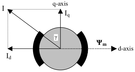
Fig. 1 Definition of dq-axes reference frame in permanent magnet machines.
As shown in Fig.1, the q-axis current $I_q$ creates a magnetic field in the q-axis that interacts with the magnetic field of the permanent magnets $\Psi_m$ lying in the d-axis to generate torque. The d-axis current $I_d$ creates a magnetic field in the d-axis, which can be used to weaken the magnetic field of the permanent magnets when chosen negative (field weakening operation above base speed). With a salient rotor construction (q-axis inductance is larger than d-axis inductance $L_q>L_d$), a negative d-axis current can also contribute with reluctance torque according to the classical torque equation of a permanent magnet machine: $$T=\frac{3}{2}\frac{p}{2}\left(\Psi_mI_q + (L_d-L_q)I_qI_d\right)$$ where $p$ is the number of poles.
As shown in Fig. 1, the current vector is defined by its peak value $I$ and its current angle $\gamma$ towards the q-axis. The relationship between the amplitude and phase angle of the current vector and the dq-axes components is given by the following equations: $$I_q = I\cos{\gamma}$$ $$I_d = -I\sin{\gamma}$$ $$I = \sqrt{I_d^2+I_q^2}$$ $$\gamma = tan^{-1}\left( -\frac{I_d}{I_q}\right)$$
Fig. 2 shows an example of the airgap flux density of a surface-mounted permanent magnet machine fed with q-axis current only. The figure shows how the magnetic field from the permanent magnets and the armature reaction interact, and how their superposition gets affected by saturation and the slotting effect due to the stator slot openings. It can also be seen from Fig. 2 that when the current angle $\gamma$ is approaching 90 electrical degrees (negative d-axis current only), the armature reaction is directly opposing the magnetic field from the permanent magnets. As a consequence, the risk for demagnetization of the permanent magnets increases with an increasing current angle.
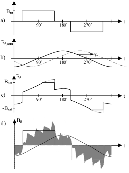
Fig. 2 Airgap flux density: a) from radially magnetized surface-mounted magnets (ideal), b) from armature reaction only (ideal), from both permanent magnets and armature reaction (c) ideal, with q-axis current only, d) simulated).
Read about another glossary term