
Advance angle
In a brushless DC (BLDC) machine, the advance angle defines the timing of the current commutation in relation to the rotor position.
As shown in Fig. 1, the current advance angle of a BLDC machine is generally in the range between 0 electrical degrees (current in phase with back-EMF) and 90°. In analogy with the BLAC machine, an advance angle of 0° corresponds to pure q-axis current, while an advance angle of 90° corresponds to pure negative d-axis current. However, in contrast to the BLAC machine, an increasing advance angle will considerably deteriorate the amount of torque ripple produced, which makes the BLDC machine less suitable for field-weakening operation than the BLAC machine.
In practice, due to imperfections of the commutations in the converter and the inductance of the BLDC machine, the current will lag the back-EMF with an advance angle of 0°. As a consequence, the BLDC machine will not produce the maximum torque it is capable of. Therefore, in practice, it is necessary to determine the advance angle giving maximum torque depending on the machine and converter characteristics. In Emetor, however, the current commutation is assumed to be ideal and the influence of the inductance is neglected. As a consequence, the advance angle for a BLDC simulation in Emetor might be fundamentally different from the advance angle that you would use in practice. In order to get trustworthy results, you should be well aware of this fact.
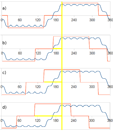
Fig. 1 Illustration of current advance angle from a) 0°, b) 30°, c) 60°, to d) 90° on the example of a star-connected BLDC machine fed with rectangular stator currents of 120° width (red: phase current, blue: phase back-EMF).
Read about another glossary term